Skip to content
Sign Up for Wholesale Access and Become a Member
Shop by Appliance
Shop by Brand
Fast Movers & Kits
Filters & Accessories
Need help?
Call or Text 909-789-0677
support@a3appliancesupply.com
Back
Shop by Appliance
Refrigerator Parts
Washer Parts
Dryer Parts
Dishwasher Parts
Range & Oven Parts
Microwave Parts
Back
Shop by Brand
Whirlpool
GE
Maytag
Frigidaire
Kenmore
LG
Back
Fast Movers & Kits
Fast Movers
Maintenance Kits
Bundle Kits
Back
Filters & Accessories
Filters
Cords & Hoses
Bulbs & Lighting
Shelves & Bins
Gaskets & Seals
A3 Appliance Supply, Inc.
Clear
Close
Login / Signup
My account
0
Cart
Your cart is empty
Shop our products
Shop by Appliance
Refrigerator Parts
Washer Parts
Dryer Parts
Dishwasher Parts
Range & Oven Parts
Microwave Parts
Shop by Brand
Whirlpool
GE
Maytag
Frigidaire
Kenmore
LG
Fast Movers & Kits
Fast Movers
Maintenance Kits
Bundle Kits
Filters & Accessories
Filters
Cords & Hoses
Bulbs & Lighting
Shelves & Bins
Gaskets & Seals
Home
GE
GE
346 products
Showing 265 - 288 of 346 products
Showing 265 - 288 of 346 products
Display: 24 per page
Display
24 per page
36 per page
48 per page
Sort by
Sort by: Best selling
Sort by
Featured
Most relevant
Best selling
Alphabetically, A-Z
Alphabetically, Z-A
Price, low to high
Price, high to low
Date, old to new
Date, new to old
View
GE
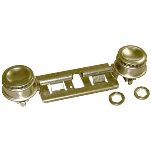
GE WB16K10026 Double Burner Assembly – OEM Replacement
Sale price
$62.37
Add to cart
Quick view
GE
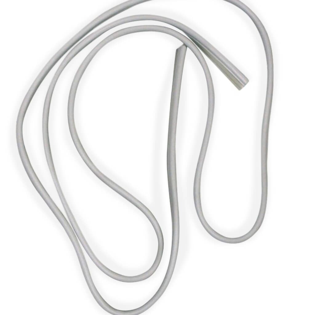
GE WD08X10057 Door Gasket – OEM Replacement
Sale price
$97.26
Add to cart
Quick view
GE
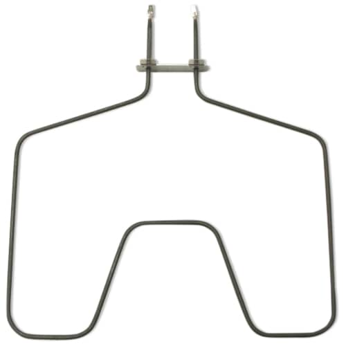
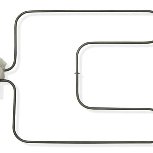
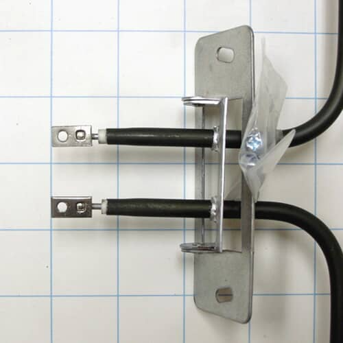
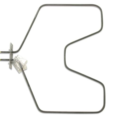
GE WB44K5012 Bake Element – OEM Replacement
Sale price
$37.99
Add to cart
Quick view
GE
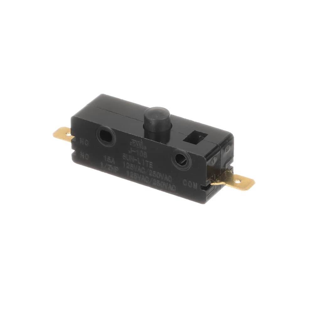
GE WD21X10261 Switch Interlock – OEM Replacement
Sale price
$42.47
Add to cart
Quick view
GE
GE WB44X200 Range Bake Element – OEM Replacement
Sale price
$41.20
Add to cart
Quick view
GE
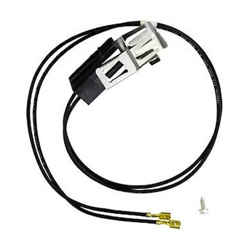
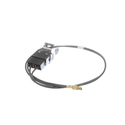
GE WB2X8228 Clip Receptacle – OEM Replacement
Sale price
$34.80
Add to cart
Quick view
GE
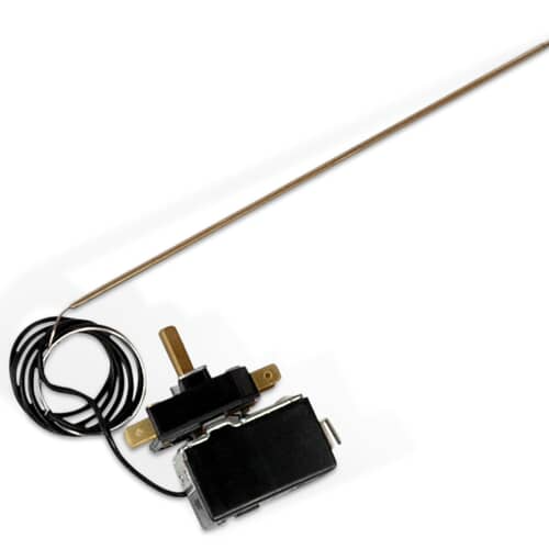
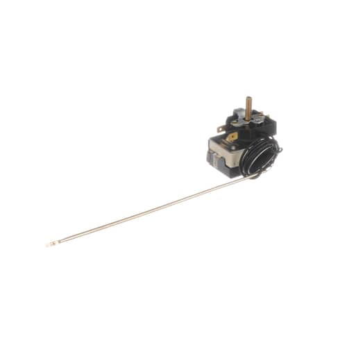
GE WB20K10026 Electric Thermostat – OEM Replacement
Sale price
$76.90
Add to cart
Quick view
GE
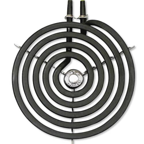
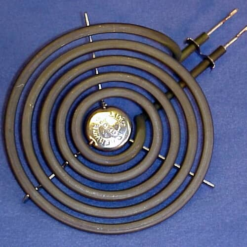
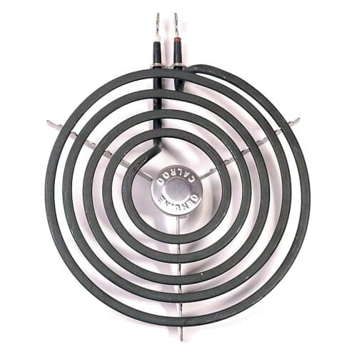
GE WB30M1 6" Surface Element – OEM Replacement
Sale price
$48.60
Add to cart
Quick view
GE
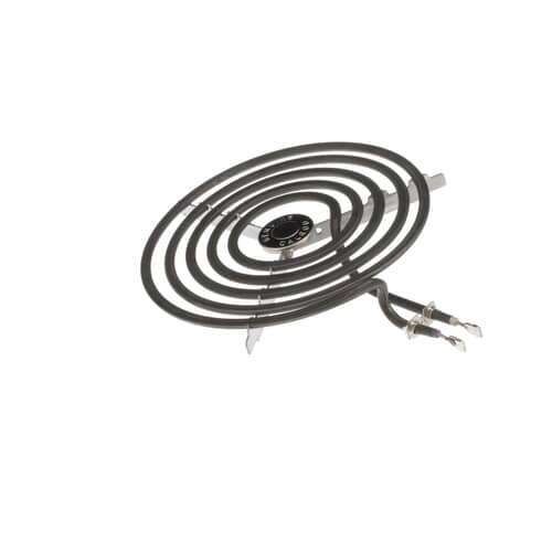
GE WB30T10074 Surface Element – OEM Replacement
Sale price
$64.11
Add to cart
Quick view
GE
GE WB44X5082 Range Bake Element – OEM Replacement
Sale price
$49.45
Add to cart
Quick view
GE
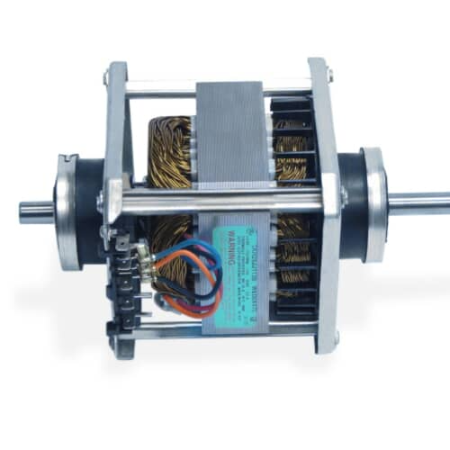
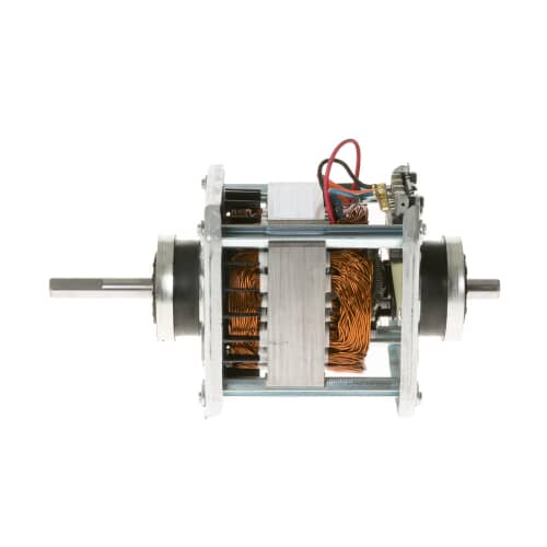
GE WE17X10010 Motor Kit – Genuine OEM Part
Sale price
$171.50
Add to cart
Quick view
GE
GE WE14M124 Top Bearing Assembly – OEM Replacement
Sale price
$79.76
Add to cart
Quick view
GE
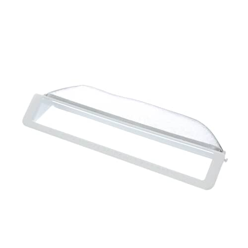
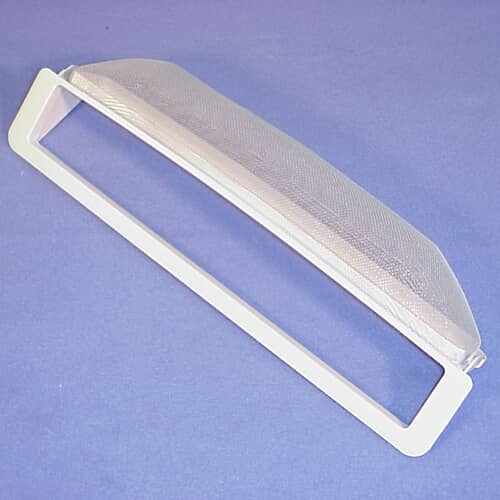
GE WE18X54 Dryer Filter Assembly – OEM Replacement
Sale price
$75.06
Add to cart
Quick view
GE
GE WE4M255 Resistor – OEM Replacement
Sale price
$38.04
Add to cart
Quick view
GE
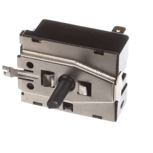
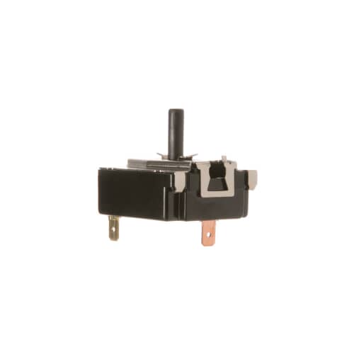
GE WE4X881 Rotary Start Switch – OEM Replacement
Sale price
$60.74
Add to cart
Quick view
GE
GE WH1X2721 Knob & Clip Assembly – OEM Replacement
Sale price
$23.73
Add to cart
Quick view
GE
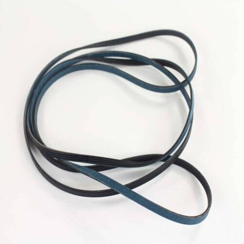
GE WE12X10009 Dryer Drive Belt – OEM Replacement
Sale price
$78.18
Add to cart
Quick view
GE
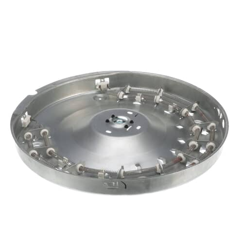
GE WE11M23 Dryer Heater Housing Assembly – OEM Replacement
Sale price
$144.49
Add to cart
Quick view
GE
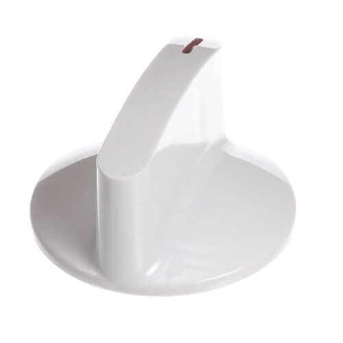
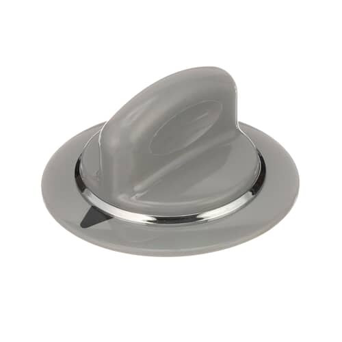
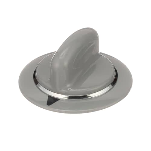
GE WE1M964 Dryer Timer Knob Assembly – OEM Replacement
Sale price
$33.05
Add to cart
Quick view
GE
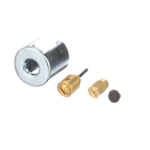
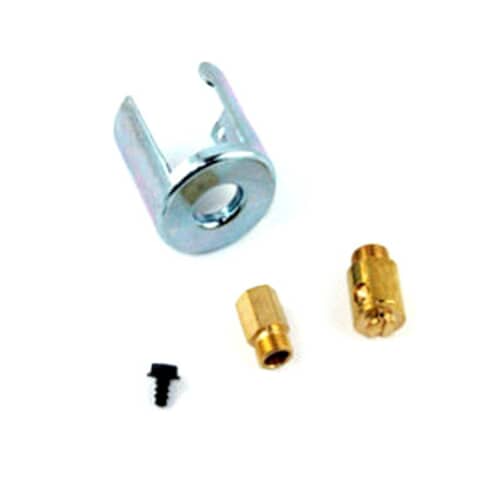
GE WE25X217 LP Gas Conversion Kit – OEM Replacement
Sale price
$71.66
Add to cart
Quick view
GE
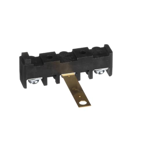
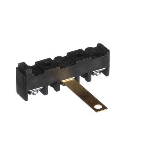
GE WE4M325 Terminal Block & Ground Strap – OEM Replacement
Sale price
$37.98
Add to cart
Quick view
GE
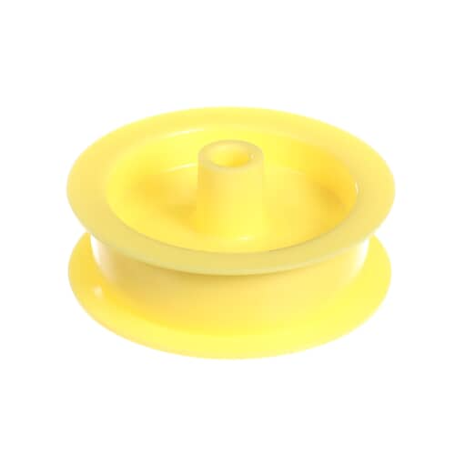
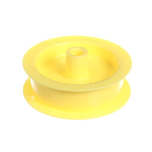
GE WE12X83 Dryer Idler Pulley – OEM Replacement
Sale price
$31.41
Add to cart
Quick view
GE
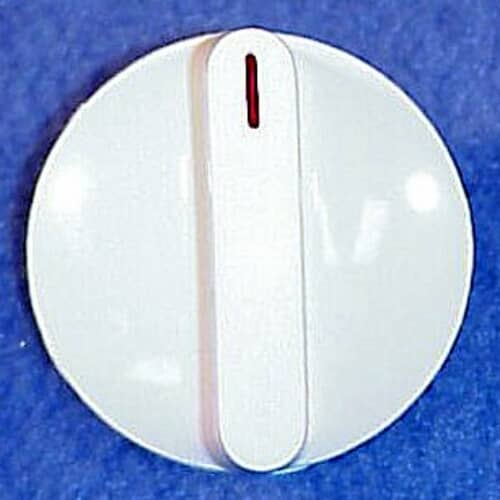
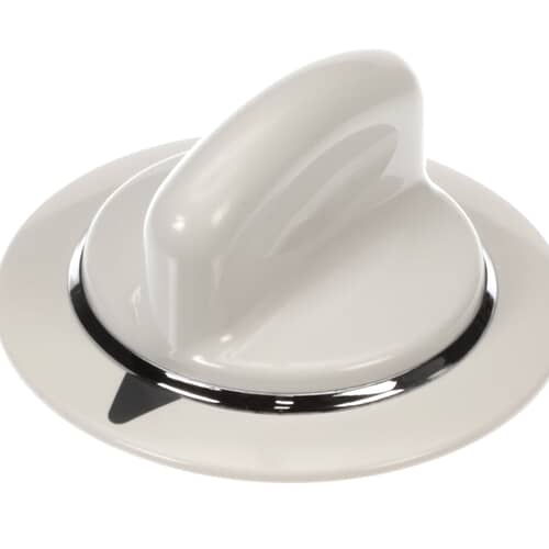
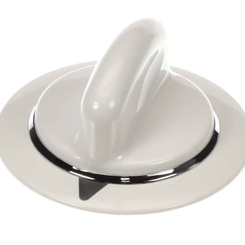
GE WE1M654 Dryer Timer Knob – OEM Replacement
Sale price
$39.93
Add to cart
Quick view
GE
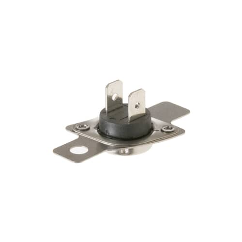
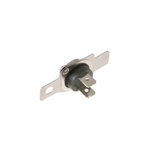
GE WE4M398 Dryer Inlet Control Thermostat – OEM Replacement
Sale price
$47.37
Add to cart
Quick view
Previous
1
…
10
11
12
13
14
15
Page 12 / 15
Next
Recently viewed
Opens in a new window.